BPMN 1.2 tutorial
Introduction
This article provides a short overview of BPMN 1.2. BPMN is a so-called flowcharting notation language for defining a business process in terms of connected activities, events and gateways. This article is "work in progress", e.g. so far it basically just includes an overview of BPMN elements. Interesting commented patterns and examples are missing - Daniel K. Schneider 17:31, 29 July 2010 (UTC).
Target populations are educational/instructional technologists and other persons interested in educational design languages and educational modeling languages. However, most technical information also may be of interest to anyone interested in Business Process modeling. We suggest reading a tutorial by example first, e.g. try BPMN by example from Bizagi. A list of other tutorials is also available in the BPMN overview article.
BPMN is a Business Process Diagram (BPD) language that includes functionalities found in workflow modeling languages used in computer science, e.g. UML activity diagrams and UML use case diagrams. However, BPMN is more complex and seems to be better suited to model workflows that involve humans. The "Business" word in standards like BPMN, BPEL, etc. reflects the fact that this language was specifically developed by and for the business community. BPMN can be used to model any "bureaucratic" process that involves both humans and computers (including web services). BPMN (and particularly the upcoming 2.0 version) may have interesting potential for education, in particular for modeling and implementing activity-based learning designs such as CSCL scripts.
BPMN can be used at several levels:
- It can be used to informally describe workflows in the same ways that people use flow charts or directed concepts maps (such as Compendium LD in education).
- It can be used as a formal diagramming tool that respects the BPMN specification, including various constraints and suggested use of attributes.
- It may be used to model an executable (business) process, i.e. models are meant to be translated/exported into an execution language like BPEL. Several commercial tools include this functionality.
See also:
- Business process modeling (for background information)
- BPMN (overview and links) and BPMN 2 tutorial
- Diagramming software (for general purpose tools, some of which allow to draw some kind of BPMN)
- BPMN and BPMS software
Overview of BPMN 1.1/1.2 (2008/9)
According to the BPMN 1.2 specification, “The primary goal of BPMN is to provide a notation that is readily understandable by all business users, from the business analysts that create the initial drafts of the processes, to the technical developers responsible for implementing the technology that will perform those processes, and finally, to the business people who will manage and monitor those processes. Thus, BPMN creates a standardized bridge for the gap between the business process design and process implementation. Another goal, but no less important, is to ensure that XML languages designed for the execution of business processes, such as BPEL4WS (Business Process Execution Language for Web Services), can be visualized with a business-oriented notation.”
BPMN 1.2 is a so-called notation language, i.e. it allows to "draw" the design of a business process, i.e. the coordination of human and computer workflows in an organization. In computer science, its closest kin is the UML activity diagram. Like some UML languages, BPMN is a kind of flow-charting language. However, the specification includes an informal annex that defines possible mapping to BPEL (more precisely the BPEL4WS version), a process execution language. In addition, vendors also could implement translators to any sort of execution environment. BPMN 2 (to be finalized by the end of 2010) defines its own serialization format.
BPMN was created with business execution languages and web services in mind and it is based on a mathematical foundation, the Pi-Calculus. However, in practice. BPMN 1.2 only has "execution" and "web services" in mind, meaning that bindings for the latter are not formally "included" in the specification. This means that you either can use BPMN as descriptive modeling language only or probably face some vendor lock-in if you are looking for a full modeling-implementation-execution pipeline.
BPMN core elements
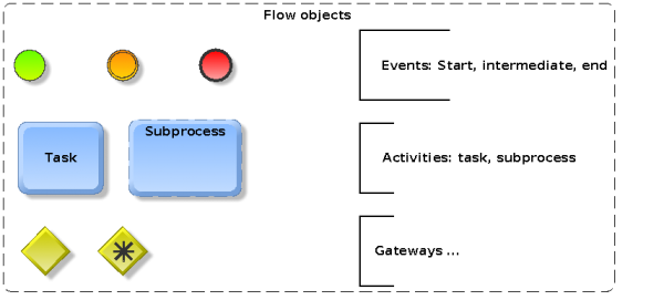
BPMN is a fairly complex and rich language. According to the 1.2 specification, BPMN has eleven core elements for defining a business process and that can be grouped in four categories:
- Flow objects, in particular activity nodes describing work performed by humans or by software applications, events, and control nodes that organize the flow of control between activities.
- Artifacts provide either annotations or describe data objects
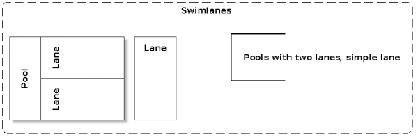
- Pools (Swimlanes) organize workflows by performing entities and communication (messaging/collaboration) between these entities.
- Connecting Objects connect flow objects through sequence flow within a pool and flow objects through message flow across pools.
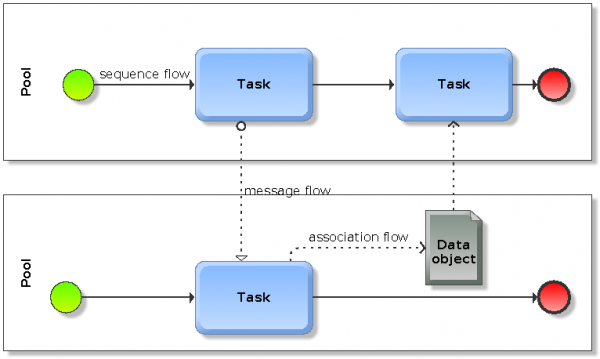
A most simple example with two pools is presented at the end of this subsection. Let's now shortly introduce the eleven basic BPMN 1.x elements.
- (a) Flow Objects
- define the behavior of a business process and are the most important constituent elements of process diagrams.
- Types: (1) Event (start, intermediate, end), (2) Activity (task, sub-process and process), (3) Gateway (various)
- (b) Artifacts (Artefacts)
- are used to provide extra information about the process
- Types: (4) Data Object, (5) Group, (6) Annotation
- (c) Swimlanes
- group elements into processes performed by entities
- Types: (7) Pool, (8) Lane
- (d) Connecting Objects
- connect flow objects and artifacts (above) to each other
- Types: (9) Sequence Flow, (10) Message Flow, (11) Association.
- A simple example
With the help of these connecting objects, process diagrams can be structured in three ways:
- Sequence flows define an order of activities performed in a process. Each flow has a single source (a start event, activity or gateway) and a single target (a end event, activity of gateway). Elements of a sequence flow are connected with solid arrows.
- Message flows either connect two pools or flow objects within these pools. As opposed to sequence flows, they cannot connect objects within the same pool. Message flows are represented with dashed arrows.
- Associations associate flow objects with information and artifacts and are drawn with dotted lines.
The following figure implements a simple workflow with two processes that are coordinated by message flows, i.e. dotted arrows. Each process must have a start (the green circle) and an end (the red circle). It then should include at least an activity, in our case 1 or two simple tasks. Flow objects within a same process (e.g. start event, task and end event) are connected by solid arrows representing sequence flows.
Message and sequence flows are usually drawn orthogonally, i.e. sequence goes in one direction (either top->down or left->right) and messages in the other as the picture above shows.
The BPMN 1.2 extended set
Most of the eleven core elements can by typed, e.g. an event can be either of type start, intermediate or end. These sub-types then can be further typed by specifying an event trigger. As an example, the start event may be a message start event meaning that the process is triggered (started) after receiving a message from another participant.
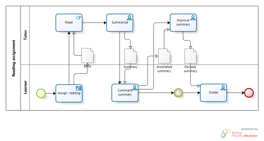
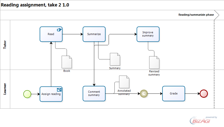
Below is a simple example of a pedagogical scenario. Tutor hands out a reading assignment, learner reads the book and then creates a summary with a online tool. The teacher will receive a message and then can provide some feedback. The student then has to revise it and the teacher will grade it after some deadline.
As you can see in the figure and as we shall explain later, tasks also can be typed. In this simple scenario, we use manual tasks ("user reading a book"), computer-supported user tasks (marked with the hand symbol) and a message task.
Notice: I am not sure how data objects should be used. In the model, the book and summary are linked to more than one task, this may not work in some vendor frameworks as we found out. In addition, data objects are not a necessity, since data also can (invisibly/implicitly) attached to tasks, flows and events. Anyhow, it seems to us that dataflow is somewhat underspecified in BPMN or in other words, BPMN focusses on the organization of tasks and dataflow is something that has to be dealt with "behind" the notation language. Daniel K. Schneider 16:35, 20 July 2010 (UTC)
We will introduce the various components of the extended BPMN set in the following sections. But before, we shortly look some syntactic and execution issues.
BPMN process syntax and semantics
It is important to understand that there are many restrictions on how BPMN elements may be combined. Some of these are in fine print in the specification. Overal, the specification is easy enough to understand, but it is very difficult to learn global use case pictures, i.e. what combinations of elements one should use for a given kind of process. The fact that there are often many quite different alternatives for modeling a same pattern which is a bit confusing.
In addition, since BPMN is a pure notation language, a modeler has the liberty to design a process at various levels of abstraction/precision. However, once he uses a commercial framework that integrates BPMN with a data modeling and process execution framework this doesn't hold true anymore. Also, since translation from BPMN to an execution language like BPEL is tricky, some diagrams that are correct in principle may not be validated by the tool.
The first difficult is to understand how to partition large workflows that engage more than one actor and more than one organization. As a ground rule (but the specification isn't very specific about this):
- To diagram a single workflow within an organization (whatever that means) use sequence flows. Each participant will have a lane in the same pool.
- To diagram loose collaboration between organization, use message flows and a pool for each organization.
This being said, it is not obvious to us what should be considered an organization. E.g. in an educational context one may model a pedagogical scenario with a single pool, i.e. as an integrated workflow or with more than one pool, e.g. at least one for the instructor and another for the student(s).
Overall, the rules for connecting elements of a business process are fairly simple. Look at the previous figures for examples that show simple processes that include two participants' sequence flows and a message flow between these participants. Let's now summarize the rules for connecting elements:
- (1) Sequence flow rules
- In principle, any flow object of start event, intermediate event, task, sub-process, gateway can connect to intermediate event, task, sub-process, gateway and end event. Or the other way round: no object can connect to a start event, and end events cannot connect other events.
- Objects within subprocesses cannot connect to objects outside this process.
- Sequence flows cannot cross a pool boundary, use messages or signals for this purpose.
Put simply: As long as flow objects sit inside a pool you can try to connect these in almost any way. However, there are many exceptions to this general rule and that are detailed in the specification. In principle, a BPMN editor ought to refuse illegal connections...
- (2) Message flow rules
- pools, subprocesses, tasks, intermediate message events and end message events can connect to pools, subprocesses, tasks, start message events and intermediate message events. Within this list, only start and event events behave differently: Start message events can only receive a message, but not send a message. End message events can only send messages but not receive messages. Let's recall that start events start a process and end events end a process.
- (3) Exception flow
A third kind of flow besides sequence and message flow is exception flow (errors, compensations, etc.). We will address this issue in a future revision of this piece ...
- (4) Drawing rules for connecting lines and arrows
There are no limitations with respect to drawing, exit and entry points of connecting lines can be anywhere on the border of an object. However, it is obvious that a flow diagram should be as simple as possible (mostly straight lines and little overlaps).
BPMN attributes
BPMN includes attributes at several levels:
(1) A BPMN diagram itself has a few attributes like ID, name, author, version, a documentation and finally a list of pools (i.e. processes)
(2) There are 11 BPMN attributes for processes (pools)
(3) There are few common BPMN attributes for graphical objects. The most important attributes are defined for each type and sometimes sub-type as we shall see later.
Attributes often just reflect what the modeler is drawing (e.g. a task with two markers). But they also are used to add extra information that is (per default) hidden from the diagram, e.g. expressions to be evaluated in tests (gates).
Data modeling and execution
BPMN 1.x does not specify any language that might be used as input for an workflow execution engine, it just specifies an informal way to map BPMN to BPEL4WS. BPMN 1.x doesn't even specify a representation (serialization) language for the drawings, meaning that you can't export/import a drawing from one editor to another. Some vendors provide tools for exporting/importing their BPMN 1.x diagrams to their own workflow/web services framework. Some can import/export to XPDL (a serialization language for process diagrams) and BPEL (a BPM execution language), however many authors claim that BPEL is not the holy grail for BPM.
Put simply, according to the specification, BPMN drawings must be neither portable nor executable, although several vendor-specific solutions do exist for both.
Another difficulty relates to the sometimes not very clear connecting objects semantics of BPMN 1.2 or maybe the implementations we played with were incomplete. It seems that the question whether BPMN Semantics is "Vague" or Just Hard to Code? remains open. Finally, it seems that a given problem can be modeled in many different ways and we wonder how this could affect potential execution models.
Below, as an example, we sketch out a simple BPM modeling/implementation process as it is implemented in Bizagi Studio and its built-in development runtime engine.
(1) We first did another take of the simple reading/summarizing assignment example shown above. We used a single pool, i.e. considered that this scenario was to be modeled as a single integrated workflow, i.e. on process. Since Bizagi Process modeler did not accept more than a input/output association flows couple for a single data object, we then had to replicate the same data object (representing the summary a learner had to write and which we meant to be a wiki page) into three separate objects representing three versions of the same data object.
Oops tutor and learner roles are inverted .... sorry have to fix this sometimes ....
This valid model according to Bizagi process modeler did not validate with the Bizagi Studio BPM Suite, since the latter seem to require that data objects must be associated with a single task. I.e. we got 4 error messages complaining that "the data object must be associated with an activity". Actually they were associations, but two instead of one. When will CS people learn about error messaging ? .... Anyhow, we modified the model like this:
(2) In a next step (once a model is imported into a BPM(N) engine, one must model the data. The whole process is represented as one or more entities with attributes. This is IMHO the most difficult step (harder than modeling the process itself .... more later).
(3) After data is modeled, one then can define user input forms, i.e. the user interface that will be used by the execution engine.
(4) Finally the model then can be loaded and executed as "case" by an execution engine.
Activities
An activity stands for the work that an organization (e.g. a company) performs. An activity can be atomic or non-atomic (compound). The types of activities that are a part of a Process Model are:
- Tasks, represented by rounded rectangles plus (optional) additional markers;
- Subprocesses, represented by rounded rectangles. They can be collapsed (annotated with a + sign) or not;
- Processes, represented with swimlanes, i.e. either pools with lanes or simple pools. Both can be collapsed.
Simple task markers
Since BPMN is a visual notation language, "markers" are used to visually distinguish sub-classes of task objects.
An "atomic" (simple) task is a simple activity performed within an organization. A task correspond to an activity step in the process flow that cannot/should not be broken further down. Generally speaking, a task is either performed by a human, a computer application or both (i.e. a user using an application)
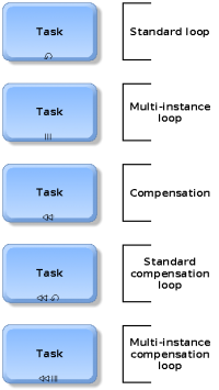
BPMN defines three basic kinds of tasks that are visually defined with markers: loops, multiple instance loops and compensations. Markers are graphically standardized and must be placed at the bottom of the rectangle. The compensation marker can be used together with loop or multiple instance. Let's now shortly describe these "markers":
- (1) Loop
Loops are repetitive tasks and include a test that defines if a task is to be repeated after each cycle of the loop (p. 54/p.65). May be used together with the compensation and multiple instance markers.
Standard loop attributes include:
- (a) LoopCondition - Expression
- Expressions are defined with respect to a scripting language, i.e. the modeler must both provide a string defining a scripting language and a valid expression.
- (b) LoopCounter - Integer
- Counts the cycles and may be used in the condition
- (c) LoopMaximum - Integer
- Defines maximum loops
- (d) TestTime - "Before"/"After"
- Defines either a while or until type of loop, i.e. the loop condition is tested before or after each cycle
- (2) Multiple instance loops
- Are a variant of loops and define for instance whether loop instances will perform in parallel or sequentially. Multiple instances also allow to define gateways after parallel path, i.e. where the "token" will go.
- (3) Compensation
- A compensation activity is special since it does not follow the normal sequence flow rules (p. 130). A compensation is one of the three types of "undo" activities: overwrite any changes (revert), do nothing, or invoke an activity that undoes the effects. The latter is called compensation. E.g. a student may turn in a late assignment and will get 10% off. If later, the student will show a medical certificate, then he will get the 10% reimbursed. However, and this is why it's not a simple undo, his assignment is still "done".
Simple task types
In addition to these main task markers representing a kind of task subclass, BPMN defines so-called task types. There is no standard graphical representation for these. Implementors can choose their own and also are allowed to add additional types (something that we certainly would need for education).
Roughly speaking, the most important task types specify which ones are automatic, IT supported or carried out manually. BPMN 1.2 defines the following seven task types:
- (1) Service task
A service task provides some sort of service like a web service or another automated application. In other words, these tasks are entirely automatic, i.e. executed by a computer.
- (2) Receive task
A Receive Task is designed to wait for a message to arrive from an external participant (relative to the Business Process). The receive task:
- can't have an incoming sequence flow
- the incoming sequence flow has a Start Event
- it is completed once the message is received
- (3) Send task
Send Task is designed to send a message to an external participant (in another pool, relative to the Business Process)
- The task is completed once the message is sent.
- (4) User task
The user task is a typical “workflow” task where a human performer performs the Task with the assistance of a software application.
- A user task is scheduled through a task list manager of some sort
- (5) Script task
A Script Task is executed by a business process engine. The modeler or implementer defines a script in a language that the engine can interpret.
- When the Task is ready to start, the engine will execute the script and the task is completed at the completion of the script.
- (6) Manual task
A Manual Task is expected to be performed without the aid of any software (like a business process execution engine, a web service or any other kind).
- (7) Reference task
When modeler may want to reference another task that has been defined (exactly the same behavior attributes)
As we already explained above, there exist some rules for both sequence flow connections and message flow connections. In addition:
- A task may have multiple sequence incoming flows although this is not recommended, i.e. one should use a gateway before the task to control flows in different paths
- ... (to do)
Sub-processes
A sub-process is a compound activity within a flow of other activities (p. 56). It has several purposes and comes in two variants and several sub-variants.
An expanded sub-process can be used to (a) associate this compound activity with exception handling, (b) with compensation handling, and finally (c) implement parallel activities in a less cluttered way than using gateways.
A collapsed sub-process may be used to hide detail within a complex process. Collapsed (only) sub-processes then can then include a combination of up to three Loop Marker, Parallel Marker, Compensation Marker, and Ad Hoc Marker. Loop cannot be used with parallel (i.e. multiple instance).
Both collapsed and expanded sub-processes can be transactions as for example defined in WS-transaction, a OASIS (formerly BEA/MS/IBM) web services specification.
BPMN processes and swimlanes
(examples needed here ....)
BPMN 1.2 allows to model the following kinds of processes:
- (1a) Private (internal) business processes
Private processes refer to processes that typically are called workflow or BPMN processes and they are internal to an organization.
- (1b) Private (internal) multiple business processes
In the business world, a pool usually represents an organization and a lane a unit within an organization. In that sense, lanes are used like the ones in UML activity diagrams, i.e. they represent "who does what". But a modeler is free to use pools and lanes for any other sort of partitioning, e.g. a lance could represent an organizational or technical function or a system.
- (2) Abstract (public) processes
An abstract or public process “represents the interactions between a private business process and another process or participant Only those activities that are used to communicate outside the private business process, plus the appropriate flow control mechanisms, are included in the abstract process. All other “internal” activities of the private business process are not shown in the abstract process. Thus, the abstract process shows to the outside world the sequence of messages that are required to interact with that business process.”
- (3) Collaboration (global) processes
A sequence flow always happens in a so-called pool or in a lane that is part of a pool. Both simple pools or pools with lanes are called swimlanes. Each swimlane usually represent a different independent participant that intervenes in the process. A diagram without pools, implies one implicit pool.
Gateways
“Gateways are modeling elements that are used to control how Sequence Flow interact as they converge and diverge within a Process. If the flow does not need to be controlled, then a Gateway is not needed. The term “Gateway” implies that there is a gating mechanism that either allows or disallows passage through the Gateway--that is, as Tokens arrive at a Gateway, they can be merged together on input and/or split apart on output as the Gateway mechanisms are invoked.” (BPMN 1.2 specification, p 70).
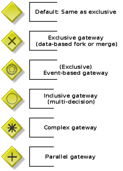
Gateways are graphically represented as diamonds like in many other flow chart languages. However, BPMN Gateways are not just exclusive branchings like in traditional flowcharts. IN BPRMN, gateways are used to represent many kinds of sequencing behavior:
- Decisions/branching (exclusive, inclusive, and complex),
- merging,
- forking,
- and joining
In that sense a gateway is a collection of gates that will control input and output flow, i.e. converging and diverging flows. A particular gateway can have multiple input and output gates, i.e. control both diverging and converging flow. However, it is recommended that a single gateway either models diverging or converging, but not both.
Graphically, incoming and outgoing sequence flows can connect to any boundary position.
The specification includes many "fine" details which we can't address in detail here. The most important general rules are the following:
- A gateway cannot be a source or a target for a message flow.
- A gateway can be the source or the target or both source and target of a sequence flow, i.e. connect to tasks, subprocesses, other gates or events.
While it is fairly easy to understand what various types do in general both with respect to decision (forking/diverging) and merging (converging), it is not straightforward to understand what kinds of expressions are evaluated and where they are.
- Sometimes (e.g. for complex gateways) the expression is attached to the gateway,
- sometimes (e.g. for exclusive data gateways) the expression sits in the outgoing sequence flows,
- and sometimes (e.g. the "message names" in exclusive event gateways) sit in the flow elements attached to the outgoing sequence flows
.... a bit confusing and not very clearly spelled out yet below- Daniel K. Schneider 16:57, 26 July 2010 (UTC)
Exclusive data gateways
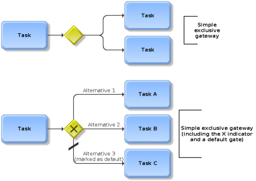
An exclusive (XOR) gateway usually represents a decision, i.e. what path the sequence flow in a business process should take. A data token that traverses the process flow will arrive at this so-called XOR gateway. One can think of gateway as a "question" or test to be asked and the answer will then determine the flow. Let's recall that gateways do no represent any user or machine action. They just represent just "gates" that determine flow with respect to data or events.
Conditions (i.e. gates) of the exclusive (XOR) gateway are tested in sequential order. The first one that evaluates to TRUE will open the gate and no further evaluation is done. Again, this means that only one path will be selected. One also can specify a default gate. It will be considered last, i.e. if all others fail.
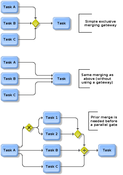
In addition, exclusive gateways also may be use to model an exclusive (XOR) merge of data flows. Basically this means that only one input is chosen (i.e. the first that arrives). Most often, it is not necessary to model an exclusive merge with a gateway, since a task also can accept more than one input flow. Using an exclusive gateway for merging is required when alternative sequence flows are ultimately merged in a parallel gateway. The latter will wait for all incoming sequences and therefore there should be only a single input path from a decision.
Exclusive event-based gateways
Event-based gateways can be used to handle more distributed processing, e.g. across pools. This type was derived from BPEL the pick activity “through which you can specify that the business process should await the occurrence of one event in a set of events” (A Hands-on Introduction to BPEL). More simply: Arrival of a message can be described as an event occurrence.
With respect to converging flows (merging), event-based gateways behave in the same way as data-base gateways (Specification, p. 77).
“On the output side, the basic idea is that this Decision represents a branching point in the process where the alternatives are based on events that occurs at that point in the Process, rather than the evaluation of expressions using process data. A specific event, usually the receipt of a message, determines which of the paths will be taken.” (p.77)
As an example, image that a learners submits a proposal to a tutor and then waits for a positive or negative answer. The tutor's answer will then determine what path the student should take next.
It is important to understand that the name (identity) of the message and not the content of the message will determine the branching. Furthermore, although data- and event-based gateways may look the same, they don't work in the same way. In the former case, the gateway defines series of sequentially ordered test, i.e. one for each gate. In the latter case, the tests for the gates are defined through either receiving tasks or intermediate events attached to each branch.
Therefore, event-based exclusive decisions must have its outgoing sequence flows target either a task of type Receive or an intermediate event, typically with a Messages or Timer trigger (but any trigger is allowed since all events do indeed catch events ...)
Inclusive Gateways
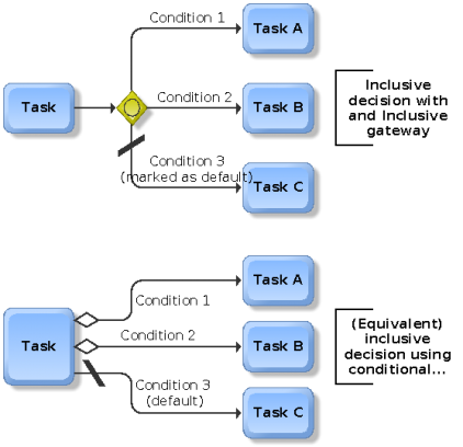
Inclusive diverging flows model a series of conditional expressions of which several can true (and at least one ought to be true), i.e. they model so-called OR decisions and merges.
Inclusive (OR) decisions means that one or more outgoing flows may be taken. It is mandatory to specify a default flow (at least in the sense that one expression always will evaluate to TRUE, else the process can become stuck).
Inclusive OR merges means that the process flow will continue using one or more incoming sequence flows (not sure about this, the alternative is that the process will continue as soon as the first one arrives ...)
Complex gateways
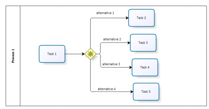
“When the Gateway is used as a Decision, then an expression determines which of the outgoing Sequence Flow will be chosen for the Process to continue. The expression may refer to process data and the status of the incoming Sequence Flow. For example, an expression may evaluate Process data and then select different sets of outgoing Sequence Flow, based on the results of the evaluation. However, the expression should be designed so that at least one of the outgoing Sequence Flow will be chosen.” (BPMN 1.2 specification, p 83).
In terms of programming, a complex decision gateway is simply a complex expression that will determine which of the outgoing flows (alternatives) will be chosen for the process to continue. The evaluation expression is attached to the gateway, e.g. a designer has to edit the properties of the complex gateway object and define expressions for each of the branches.
A complex merge (the opposite) will define which incoming sequence flow will be required for the process to continue. Again, the expression should be designed to avoid stalling. I.e. the show must go on based on one or another flow.
Attributes (p. 84)
- IncomingCondition (0-1) : Expression
- If there are multiple incoming Sequence Flow, an IncomingCondition expression MUST be set by the modeler. This will consist of an expression that can reference Sequence Flow names and/or Process Properties (Data).
- OutgoingCondition (0-1) : Expression
- If there are multiple outgoing Sequence Flow, an OutgoingCondition expression MUST be set by the modeler. This will consist of an expression that can reference (outgoing) Sequence Flow Ids and/or Process Properties (Data).
Parallel Gateways
“Parallel Gateways provide a mechanism to synchronize parallel flow and to create parallel flow. These Gateways are not required to create parallel flow, but they can be used to clarify the behavior of complex situations where a string of Gateways are used and parallel flow is required.” (p. 85).
Best practice suggests that modelers should use these parallel gateways instead of directly connecting flow objects.
When a diverging flow has been defined, all gates will be selected, i.e. the sequence flow will go through all branches. With respect to synchronizing, the gateway will for a signal (the token) from all branches before it opens.
BPMN 1.2 event elements
An event is something that "happens" during a process and it will affect the flow of the process. It usually has either a cause or an impact or both. Events typically do not depend on the user, but on an external factor, e.g. what another user represented by another pool does.
In more operational terms, one also could say that events will affect the sequence of the timing of process activities.
There are three main types of events: start events, intermediate events and end events.
- Events are represented as small circles and fills must be either white (no color) or use a clear color.
- Start events have a fine stroke, intermediate events a double fine stroke, and end events a fat stroke.
- Inside the circle there can be shape that helps identifying a trigger. As you can see below, the various event types can be associated with various triggers, but not all triggers are available for each of the three start, intermediate and end event.

Start Events
Start events indicate the initiation of a process and are usually associated with a trigger. The five types of triggers defined by v. 1.1 are represented with graphical markers.
- Plain (generic) start events
- do not specify any trigger
- Message start events
- start when a message is received from another participant
- Timer start event
- indicate a given time/date for starting
- Conditional start events
- a process is triggered when certain business conditions become true.
- Signal start events
- A signal arrives that has been broadcasted from another process
- Multiple start events
- Defines multiple ways of triggering a process.
Intermediate events
There are 10 types of intermediate events in BPMN 1.2. All of these can respond to (catch) a trigger and some can set off (throw) a trigger. Catching events (only) also can be directly attached to the boundary of an activity.
Events are drawn as double circle. Catching event markers are drawn with strokes and throwing events are drawn filled.
- Simple ("none") intermediate event
- Events in the main flow of the process that are not further specified.
- Message (catching and throwing) intermediate events
- When catching, a message arrives from a participant and triggers the Event. If the process was waiting for the message it then can continue. Messages also can be used for exception handling, i.e. the process will continue differently.
- When throwing in normal flow, a message is sent to another participant.
- Summarized, messages are used to receive/send between 2 participants A and B.
- Timer (catching) intermediate event
- A set time/date will trigger the event, i.e. it inserts a delay. For example, it could be used to model a deadline for turning in an assignment.
- Error (catching) intermediate event
- Only can be used in the boundary of an object. Can either catch a named error or all errors if none is specified
- Cancel (catching) intermediate event
- This cancel event must be used in the boundary of a transaction subprocess. It can be triggered either by a message or by a cancel end event in the subprocess.
- Compensation (catching and throwing) intermediate events
- When catching, a compensation activity attached to this event will be triggered.
- In normal flow, when throwing an event is defined, this event will be triggered, else "compensation" is broadcasted to all activities in the process.
- Conditional (catching) intermediate event
- Event is triggered when a condition becomes true
- Link (catching and throwing) intermediate event
- Links connect two sections of a process (at the same level), e.g. to implement looping, goto or simply move to a "next page". There can be multiple source, but only one target link.
- Signal (catching and throwing) intermediate event
- Signals can be sent and received across process levels, pools and even diagrams. As opposed to messages, targets cannot be identified, i.e. there is always a specific source (throwing) but specific target. In other words, a signal is like a flare. Catching events must be attached to the boundary of an activity.
- Multiple (catching and throwing) intermediate event
- In normal flow, a multiple event can either catch or throw various events. When attached to an activity it can only catch.
End events
- Simple ("none") end event
- showing that and where a process ends
- Message end event
- indicates that a message is sent to a participant when the end of the process is reached
- Error end event
- an error code should be generated. This code then can be caught by an error catching intermediate event in the parent. If there is none, then the system also can handle this.
- Cancel end event
- is only used in transaction sub-processes and will signal that this transaction should be cancelled.
- Compensation end event
- can either compensate an activity that is identified. Otherwise all activities in the process can be subject to compensation if they have a compensation intermediate event attached.
- Signal end event
- a signal is generated. It will be broadcasted to any process (i.e. signal catching events) that can receive it. A signal is different from a message. The latter always has a source and a target.
- Terminate end event
- triggers an immediate end to the process and all its activities. The process is ended without compensation of event handling.
- Multiple end event
- multiple consequences of ending the Process.
Artifacts
Data objects
Data objects do not directly affect sequence or message flows. They provide information about what the process does, i.e. how data, documents and and sort of other objects are used and updated during the process.
BPMN doesn't model artifacts themselves, this task is left to vendors according to the specification (p 93.). We found the specification to be very vague with respect to these objects and indeed various modeling tools we tried (Aris Express, Bizagi Process Modeler, Bizagi Studio) won't allow to use data objects in the same way - Daniel K. Schneider 17:58, 21 July 2010 (UTC).
Data objects are generally associated with flow objects (typically a task). In that case they can represent input or output with directional arrows.
They also can be attached to sequence and message flows in order to show what data are sent from one activity to another. In the case of a message flow, the data object represent the "content" (payload) of the message itself.
The data object includes a name, a state and various modeler-definable properties. The latter then can be mapped to a data model in an execution engine.
Some design patterns for connecting objects
(to do)
Examples
Development of courses in a specific e-learning center
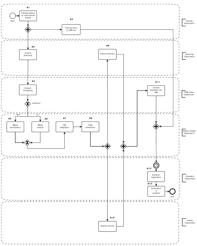
González-Ferrer et al. (2009:20), in a paper about planning and scheduling (P&S) presented “An example organisational process modeled using the BPMN graphical notation, describing the development of courses in a specific e-learning center. On the right side, text annotations boxes show the lane represented with point lines on the left; the boxes, named A1-A13, represent the activities; the arrows represent the transitions; the elements with the symbols ’x’ and ’+’ are the exclusive-OR and parallel gateways; the participants are not represented graphically, and can only be explored within the BPM modelling tool. This model can be serialized as a XPDL stream.”
Model of a discussion
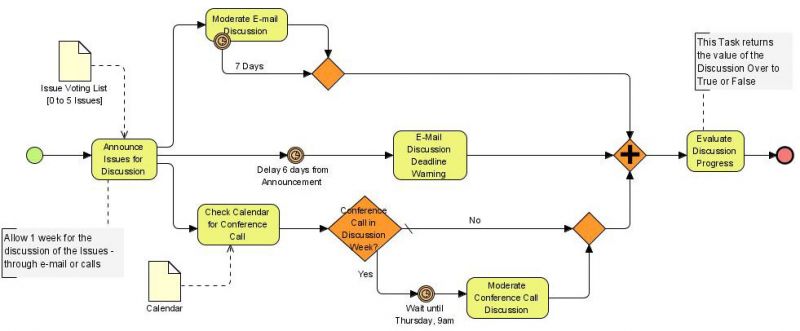
Email voting process

Model of surgery programming
The process model presented by Roja et al. (2008) shows at a high level abstraction the programmed surgical patient (PSP) process and the activities that are carried out when a patient is admitted into the hospital for the accomplishment of the surgical treatment of a disease that has been clinically diagnosed previously. This model is a result of a joint work between hospital and BPMN expert and it has been obtained through a reiterative and incremental method.
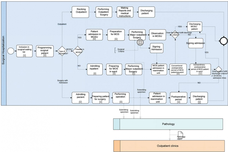
“The modelling of the programmed surgical patient process and its subprocesses has allowed to us to prepare an understandable model for the involved health professionals and make the communication of processes easier. Additionally, modelling allows early detection and correction of errors. This work is an essential previous step for further analysis and improvements in healthcare processes, including the adoption of information technology standards.” (Roja et al. (2008))
A BPMN 1 meta model
A more difficult to understand meta-model (i.e. an unofficial UML class diagram of BPMN was published by WSPER ("whisper").

BPMN 1.2 in education
In the educational and learning sciences literature, there are few traces about BPMN. Most often, BPMN is just brievly mentioned as one kind of modeling language, e.g. by Koper (2006), Spelstra (2008) Mariño et al. (2007) and Fang (2009). Paquette and Léonard argue that “Business Process Model Notations such as the BPMN specification are more restricted than learning designs on certain aspects, but they provide a larger set of conditions to control the flow of activities. Unlike IMS-LD level B and C where all the conditions are declared at the method level, BPMN conditions are visually located at the point where they are used, thus given a more transparent view of the execution flow. Also, they make important distinctions that are not present in IMS-LD such as multi-activities that are to be done separately by each actor in a group, compare to activities to be achieved by all group member cooperatively.”
González-Ferrer et al. (2009), in a paper about planning and scheduling (P&S), present an example of describing the development of courses in a specific e-learning center (see below)
In order to model educational learning designs (pedagogical scenarios), we might use a single pool to represent a strongly integrated workflow such as the ones that could be implemented with a workflow systems like LAMS and separated pools if the workflow is loosely organized such as in our C3MS project-based learning model using portalware or decoupled web 2.0 services.
We may distinguish several uses of BPMN in education:
- BPMN as an educational design language and educational modeling language (BPMN 2.0 or BPMN + BPEL)
- BPMN to model educational institutions, units, research processes etc. (i.e. use BPMN for what it is mainly meant for)
- Use BPMN as cognitive tool and/or assessment tool (Borthick, 2006) in management education, i.e. students will create diagrams in the same spirit as advocated in the concept maps in education literature.
BPMN as educational design language
Since BPMN is a workflow notation language, we can hypothesize that it suitable for modeling at least some kinds of educational workflows.
Karampiperis and Sampson (2007) argue that BPMN diagrams can be mapped to a learning modeled with IMS Learning Design and they propose an algorithm for mapping a BPEL graph structure (which may be mapped to to a BPMN in turn) to IMS Learning Design level A. At a more high-level perspective the authors suggest the following mapping between BPMN and IMS LD:
| BPMN Graphical Element | IMS LD Component |
|---|---|
| Pool | Role |
| Lane | Act RolePart |
| Activity | Activity |
| Sequence Flow | Flow of activities represented as nested Activity Structures |
| Gateway | Flow of activities represented as nested Activity Structures depending on the type of the Activity Structure (sequence of selection) |
Another argument for using BPMN as educational modeling language is that (at least in principle) BPMN is strongly tied to IT architecture and web services in particular: “There is no way to formally discover and verify some potential conflicts that may appear in learning designs before they are actually deployed into educational environments. This consequently may lead to a number of run-time issues when learning designs are deployed and used. We propose the use of the Business Process Modeling Notation as a modeling language for representing learning systems” (Siadaty et al., 2009). The fact that IMS Learning Design does not include bindings for services indeed seems to be one of the major problems with this specification and may explain why almost ten years later, there is still no decent authoring/runtime framework available.
BPMN to model processes in educational and research organizations
See the Development of courses in a specific e-learning center example for the moment...
BPMN as cognitive and assessment tool
Borthick (2006) argues that “Decades of research in cognitive psychology have led to the theory of situation model building, in which constructing one's own mental situation models constitutes the best preparation for situated action (Zwaan and Radvansky 1998; Barsalou 1999).”
“Many domains have situations or processes that professionals must understand in order to perform well. The name business process modeling indicates that the intent of BPMN is to represent business processes. The notation was developed as an approach to process representation that would be understandable to business users, business analysts, technical developers, and business managers. Students have needed very little time to understand the notation from White's (2004) short introduction to it. BPMN's generality means that this approach to accelerating learning might be applicable in business courses in which (1) situations or processes are complex and ambiguous and (2) an incomplete or faulty understanding of situations or processes leads to marginal performance. In spite of the descriptor business, the approach ought to be applicable to non-business disciplines with complex and ambiguous situations or processes. An older, more universally available modeling notation is that of flowcharts, which could be used instead of business process modeling with BPMN.” (A. Faye Borthick, 2006)
Links and bibliography
See BPMN for more links, books, software, etc. Below just a few links and references used in this piece
- Links
- Dive into BPMN
- Modeling Workflow Patterns through a Control-flow perspective using BPMN and the BPM Modeler BizAgi by Marcus Goetz, Institute of Applied Informatics and Formal Description Methods University Karlsruhe (TH).
- BPMN_Tutorial.pdf by Martin Owen and Jog Raj, Popkin Software
- BPMN by example and BPMN Tutorial/Overview (Bizagi)
- Introduction to BPMN by Stephen A. White, IBM, 1989 (?).
- Bibliography
- Barsalou, L. W. (1999). Language comprehension: Archival memory or preparation for situated action? Discourse Processes 28 (1): 61-80. PDF
- Borthick, A. Faye (2006), Improving Audit Performance With Business Process Modeling, Submission for an Instructional Effectiveness Award, Georgia State University, 2006 HTML
- Fang, Fang Chua and Lee Chien Sing (2009) Collaborative learning using service-oriented architecture: A framework design, Knowledge-Based Systems, Volume 22, Issue 4, Artificial Intelligence (AI) in Blended Learning - (AI) in Blended Learning, May 2009, Pages 271-274, ISSN 0950-7051, DOI: 10.1016/j.knosys.2009.01.003
- González-Ferrer, Arturo, Juan Fernández-Olivares and Luis Castillo (1009). JABBAH: A Java Application Framework for the Translation Between Business Process Models and HTN, ICKEPS 2009, PDF
- Karampiperis, Pythagoras and Demetrios Sampson (2007). Towards a Common Graphical Language for Learning Flows: Transforming BPEL to IMS Learning Design Level A Representations, Seventh IEEE International Conference on Advanced Learning Technologies (ICALT 2007). PDF (Access restricted) - Abstract/PDF Preprint
- Koper, R. (2006). Current Research in Learning Design. Educational Technology & Society, 9 (1), 13-22.
- Mariño, Olga; Rubby Casallas, Jorge Villalobos, Dario Correal and Julien Contamines (2007). Bridging the Gap Between E-Learning Modeling and Delivery Through the Transformation of Learnflows into Workflows, in Pierre, Samuel (Ed.) E-Learning Networked Environments and Architectures, Springer. ISBN 978-1-84628-351-2
- Mor, Yishay and Niall Winters (2008). Participatory design in open education: a workshop model for developing a pattern language, JIME 2008(13). http://jime.open.ac.uk/2008/13/
- Nijssen, G. and R. Bijlsma. A conceptual structure of knowledge as a basis for instructional designs. . in The 6th IEEE international conference on Advanced Learning Technologies, ICALT 2006. 2006. Kerkrade, the Netherlands.
- Paquette, G. and Léonard, M. (2008). A Visual Ontology-Driven LD Editor and Player: Application to the Planet Game Case Study. Journal of Interactive Media in Education. http://jime.open.ac.uk/2008/25/
- Siadaty, Melody ; Shahin Sheidaei, Milan Milanovic, Marek Hatala, Dragan Gaševic (2007). Leveraging Business Process and Rule Modeling for Developing Learning Design-based Systems, 4th Annual Scientific Conference - LORNET Research Network (I2LOR-07): Posters & Demos, Montreal, Canada, 2007. PDF, PDF
- Spoelstra, Howard; Maristella Matera, Ellen Rusman, Jan van Bruggen and Rob Koper. (2008) Bridging the gap between instructional design and double loop learning, International Journal of Web-Based Learning and Teaching Technologies, 3(1), 79-89.Abstract/PDF Reprint
- Zwaan, R. A., and G. A. Radvansky. 1998. Situation models in language comprehension and memory. Psychological Bulletin 123 (2): 162-185.
Content of this article has been taken from EduTechWiki (en) or EduTechWiki (fr) at the date indicated in the history. DKS was the main founder and main contributor of EduTechWiki. If you cite this page you also must cite and credit EduTechWiki, according to the CC BY-NC-SA license. View the pageinfo-toolboxlink for this article.
